Submission to Assignement 1 (PDF)
Colour + Illumination, Shading & Texture Mapping
- The CIE chromaticity diagram
- "pure hues":
-
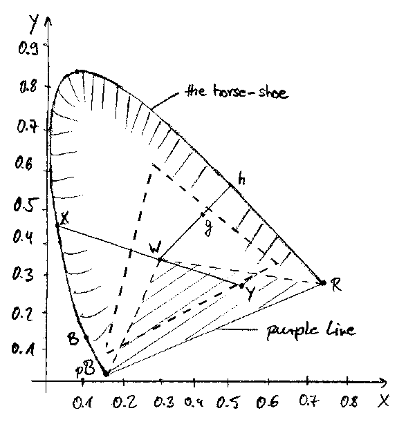
The CIE diagram forms a shape looking like a horse-shoe. It represents the
visible colours. In the middle we find "white" ['w'], corresponding
to fully unsaturated colour. In opposite the fully saturated colours
(spectral colours) are located at the edge. These are the ones with pure
hue. The hue is specified by the dominant wavelength of the colour.
- "un-mixable" colours:
-
Of course all those ones which lie outside the CIE diagram plus colours
which are inside the triangle between the left-most point of the groundline
of the horse-shoe (representing purple-blue ['pB']), the
point representing white and the right-most point of groundline (representing
red ['R']). The reason is, that
the groundline does not represent any pure colour, but is a mixture of red
and purple. Thus it's called 'purple line' (labeled as such).
For the colours in just mentioned region (i.e. ['y']), the mixture is done with the complement colour. This is specified by a ray going from the giving "colour" through "white" to the boundary of the horse-shoe. With that intersection the complement colour is found (['x']).
- dominant wavelength of non-spectral colours:
-
The dominant wavelength (=pure colour) is figured out similiar to the steps
described in the paragraph just above this question. But this time, as we
do not want to find the complement, we imagine a ray coming from the "white"
point, going throught the given "colour" (i.e. ['g']) and hitting the boundary on this
side of the colour's representation (['h']), not on the other.
- range of colours on a colour monitor:
-
The monitor gives us just a little cutout of all the colours the human eye
is able to see. That's because a monitor relies on its three phospors types,
and thus can only generate combinations of it's basic primaries green, red
and blue. The range of colours, which monitor can represent is surrounded
by a dashed thick line in the image.
- "pure hues":
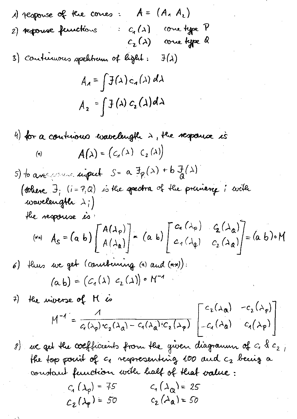
- The Alien's visual system
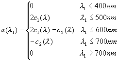
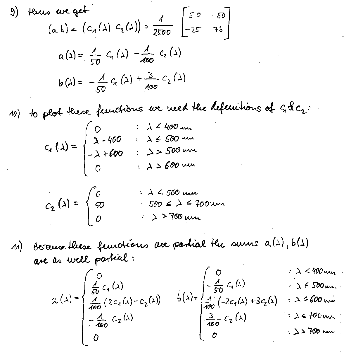
- colour matching functions:
- plot of the functions:
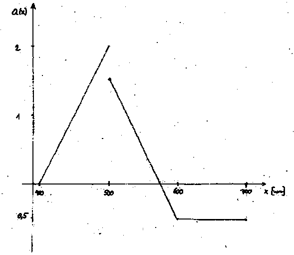 the plot of the first colour matching function
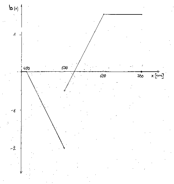 the plot of the second colour matching function
- meaning of the negative values in the function:
-
C=-aX+bY: Negative values cannot be handled like the positive values, as one cannot remove light that isn't there.
If the colour C should be constructed as the superposition of positive amounts of the primaries
X and Y, we can match it by C+aX=bY. Here every factor is possitive.
- avoidance of negative values with other primaries/inconsistence with human visable system:
-
The problem is that in the inverse matrix there are negative coefficients such that when you derive the formulas for a(l)
and b(l) there are subractions. The negative values in the matrix come from the fact, that each primary doesn't only
has to emulate one cone type but both. If this was avoided, the negative coefficients in the inverse matrix would become
zero and thus the a(l) and b(l) would be positive in the whole range.
This is inconsistent with the human visual system as the cones in the eye do not react distinctively to one particular wavelength but each cone to a range of them.
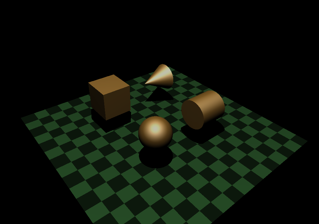
- OpenGLShadingDemo program
- change of colour when switching between "flat" and "shading"
-
Flat shading finds the colour for a whole polygone by using one point p of the polygone where a
normal n is found. With this normal a certain colour is computed at that point, which is than
applied to the whole polygone, regardless of the fact that other points of the same polygone are
in another position towards the light source and thus would be coloured differently.
Gouraud shading approaches shading a little more sophisticated. Here, the normals at each vertex of the polygone are computed and thus the colour at that points. Than an interpolation of the colour along the edges of the polygone and for the area between the edges is done. The result is an image with a nice colour distribution.
In this example, there is one case in which no difference between flat and Gouraud shading should be visible: if the light source is directly above the intersection of the diagonals of the quadratic ground plane (as if it was the top point of a pyramide). Then the angle to each vertex' normal stays constant thus the colour wouldn't change, resulting in a not shaded but constantly coloured plane.
But this case is not given here, as the light source is set asymmetrical above the ground plane. This has its middle in (0,0) in the y-plane but the light source has a z-coordinate of 8.0. Now it's clear why the colour slightly changes when switching from flat to Gouraud shading: The part of the plane whose points' normals have a smaller deviation to the light vector is rendered brighter. Points which are more distant from the lightsource and thus have a greater deviation between normal and light vector are rendered darker. When changing the shading mode this different colouring comes apparent.
- higher tessalation rate for cone than for cylinder until it appears smooth:
-
When you project a cylinder and a cone from atop on a plane, they have a very similar appearance.
Even if they are tesselated they have the same angle between adjacent side faces. This cannot be
the reason for a different appearance when rendered.
One explanation which is coherent to me could be that with the cone the space to do an interpolation between two edges along a face becomes smaller and smaller when approaching the top. The cylinder at the same level of tesselation can trick our visual system by interpolation between the different colours at the faces' edges, so it seems "round" to us. But with the cone the gradient in colour changes to fast, there is no smooth appearance anymore which could fool our eyes. Thus we need more tessalations.
- number of polygons for artifact free rendering of
- a perfectly diffuse sphere: 28-30
- a sphere with specular colour and some shininess: 43-45
- a sphere with specular colour and high shininess: ~60
- a perfectly diffuse sphere: 28-30
- addition of simple projected shadows: Image DemoScene.java
problem with light sources that are off to the side of the scene:-
In my opinion, there could only be the problem, that the objects would cast shadows on each other and the
surfaces of that objects are not planar anymore. It could even happen, that one shadow is not only casted
on one other object but partly on one and partly on another. So interaction between objects and shadows
and vice versa have to be computed. This is not possible with a simple shadowing algorithsm. You will have
to use more sophisticated methods like shadow volumes or stencil buffers.
- texture mapping
Description:-
I tried so extensively with the shadows, that I could not find enough time to do the texture mapping for a whole
'cool' scene. I had big problems in loading the images. I tried a lot, finally got it working. The scene is not
so sophisticated. It should be a "Leuchtturm" :) standing in the sea. The texture maps are loaded, but only one
is assigned to a surface. There was no more time. :( To see the full image clearly, the ambient
light should be set to the value of three. DemoScene.java To compile the source
you will need to have this (ZIP)
- change of colour when switching between "flat" and "shading"

eMail me! :)