- The projection of light patterns into a scene is called structured
lighting. The light patterns are projected onto objects that lie in
the field of view of the camera. Thus a light profile is projected onto the object.
The distance of an object to the camera or the location of an object in space
can be found through analyzing the light patterns in images. These images are taken
at different angles of object rotation. Using this data we can reconstruct the objects'
3D coordinates.
- The assignement is about reconstruction of an object using light stripe
projection. A single line is projected on an object. The object is rotated and
images are taken at predetermined angles.
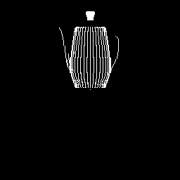
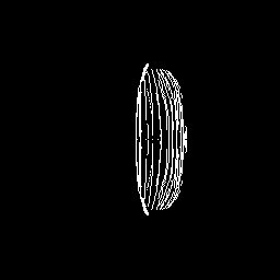
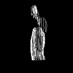
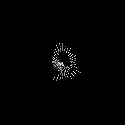
In the assignment we were given 36 pictures (10-degree steps) per object. After calculating the world coordinates of the object points, we use both projections to 2D planes and an interactive VRML representation to visualize the results.
Structured Lighting
The introduction provides the basic idea about the approach.
Single light plane approach:
The idea is to intersect the projection ray of the examined image point with the light plane. The
intersection of the light plane with the object surface is visible as a light stripe in the image.
Therefore, a larger set of depth values can be recovered from a single image which results in faster
reconstruction compared to the single spot technique. The distance value for every column stays the
same and can be stored in a look-up table (LUT). But before that is done, a calibration step has to be
performed. For simplicity let's assume, that the basic geometric calibration (camera,...) has already
been done. The Calibration of the Light Plane System is done with respect to the light projector's
coordinate system. The optical axis of the camera passes through the origin of the light projector's
coordinate system. The initial position of the calibration plane is choses such that the light profile
coincides with the middle column of the image. The ray to the border point of the image which hits
the light plane the first determines the minimal z-value, the corresponding point at the other
side determines the maximal z-value which can be found in that scene. All other points are found
by the LUT in the following way.
Preparing the LUT, extracting the light profile and calculating the depth values
We were given five calibplane images. The z-value of each image was also given. The problem is, that
in real world experiments the light stripe is normally not just one pixel wide. This observation
has a technical reason (thickness of laser is predefined) and a geometrical one (non-90degree angle
between light and camera, non-90degree angle between normal of light plane and surface normal). Thus
the light stripe forms a so called light profile which has an energy distribution similiar to an inverse
quadratic polynomial. As we are interested in the point with the most brightness we have to search for
it. This is done in beginning of the calibration step:
The plane is centered at the point, where the cameras' optical axis and the axis of the
light source intersect. Then the plane is moved in negative and positive direction along the optical axis
of the camera. The light stripe moves linearly to the right or left with respect to the direction of the
movement. Because of the linear movement of the stripe we can use the formula from the notes:
z=ax+by+c (we can reduce y because the light plane is perpendicular to xz-plane), so we have five
equations for z=ax+b. Then the a, b values are calculated. The formula of light strip plane shows the
relationship between the x (image) and z (world). We build up the table according to the corresponding
zx-value.
Reconstruction
Fist of all we parse all input pictures and search the maximum of the light stripes that occur in the
picture. This is necessary because the stripe won't have a width of only 1 pixel. It will appear with different
width, depending on the material and the angle between the camera and the light source. All pixels that
belong to a stripe and that are not maximal are set to zero, thus getting the discrete coordinates of the
points where the light has hit the object.
After that we go through each single pixel of the 36 images. We pick the pixels we are interested in (the
highlighted ones). We can generate the z-value when we refer to the x-value in the LUT. X (world) and z
(world) can be computed by rotating the point by the according angle.
We use two ways to indicate the output: One is to project the result to the xy-plane, zy-plane
and xz-plane by just setting the third coordinate to zero. Another method is to output the result
to a VRML file, which can be explored interactively.
- Implementation (in pseudo code):
	        Calibration( ){

    		   for( each calibplane image ){

    		     profile the brightest x-coordinate

    		   }

    		   build the look-up table{

    		     Z1=aX1+b;

    		     ...

    		     Z5=aX5+b;

    		     obtain a, b;

    		     for ( from 0-256 )

    		       save the z-value to corresponding x-index;

    		   }

   		}

    		Reconstruction(){

    		   for( every image taken )

    		     for( each pixel we interested ){

    		       compute the acutal x-value, y-value and z-value;

    		       write coordinate to VRML file;

    		       project on xy-plane; (ignore z)

    		       project on zy-plane; (ignore x)

    		       project on xz-plane; (ignore y)

    		     }

    		   }

    		   write data to projection images;

    		}
- We have processed all images and computed the 3D object points from the
given data. The VRML representations are very complex (a lot of points have to be displayed) and thus
they are slow while exploring. If the user wants to display them in a smaller window he is advised
to use the sphere representation (points are drawn as spheres), otherwise he/she will hardly recognize
the whole shape as the points disappear quickly at small window sizes.
| XY-projection | XZ-projection | YZ-projection | VRML-representation | |
|---|---|---|---|---|
| Model: Box | ||||
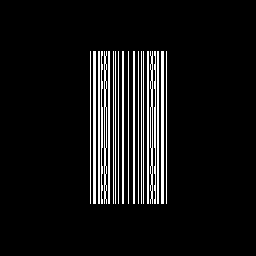 |
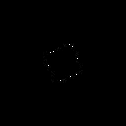 |
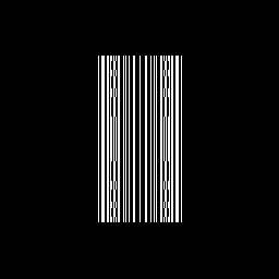 |
VRML points VRML spheres |
|
| Model: Teapot | ||||
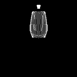 |
 |
 |
VRML points VRML spheres |
|
| Model: Teapot 2 | ||||
 |
 |
 |
VRML points VRML spheres |
|
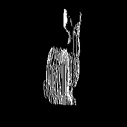
| Model: Bunny | ||||
 |
 |
 |
||
From the results we see that most of the objects were reconstructed correctly. This result was only achieved after we had scaled the y-coordinate of the image points to a reasonable degree. This is necassary because only the values of the z-dimension are calibrated. The x-values are calcullated from the given rotation angle of which the image is taken. The y-axis is never regarded in this first steps. So we don't know which y-value corresponds to how many milimetern. When calcullating the values for z and x with the LUT there is no corresponding method for the y-pixel-value (range 0 to 255). Thus there is no direct correlation between all three coordinates. In this case a scaling of the y-coordinates has to be done manually. Our factor is 1/3 which was obtain by observation until the result looked reasonable.
The one teapot (Teapot 2) is an exception to the good reconstruction results, he is not that likely to be recognized. This is the result of the location and orientation this teapot has. In contrast to the others, it's not rotating aroung itself but has a little distance to the rotation center which is the center of projection of the camera and the point of intersection of the optical axis and the light plane as well. When rotating, the light strip does not hit the object every time and if then under a maybe not suitable slope (light intensity might be to low). This leads to less points for reconstruction and the result is not that clear and unique as with different settings.-
From the view and with the human intution we can
know whether a reconstruction looks correct or not. Sometimes this
assessment is tricky to do because a simple projection of 3D object points
to 2D planes sometimes results in images which seem to show the object
deformed. Introducing shading or colours would be a possible imporvement. We
have chosen to use the possibilities of VRML files to give the user a better
opportunity to understand the recovered shape of the object.
The representation we did only contains object points (as it was
asked), no edges or even faces. We would have liked to incorporate them, but
there was the problem, that without knowledge about the real topology (all
convex surfaces or even concave ones?) it's hard to do it correctly. We
could have done it but there would have been the pending danger of
jeopardizing the result through wrong reconstructions. As the assignment
asked us to find points, not faces, our result satisfies this objective.