 PSM Surface Reconstruction & Gradient Map Generation

COMPSCI 775ST Assignment 4
From:18/09/2002
Due: 04/10/2002 2:00pm (Friday)
 PSM Surface Reconstruction & Gradient Map Generation

COMPSCI 775ST Assignment 4
Sets of three images are available in the following table. Some images
are synthetic, some are real images. The illumination directions,
ps and qs,
for the images are also given.
| Name | ps | qs | Name | ps | qs |
| beet_v1.bmp
beet_v2.bmp (Real) beet_v3.bmp |
0.031802 0.389363 |
0.556538 0.104828 |
Images/ht_1.bmp
Images/ht_2.bmp Images/ht_3.bmp |
0.0 0.0 |
0.0 1.0 |
| kugeln_1.bmp
kugeln_2.bmp kugeln_3.bmp |
0.0 0.0 |
-0.25 0.0 |
mozart1.bmp
mozart2.bmp mozart3.bmp |
-0.315 0.315 |
-0.182 -0.182 |
| porsche1.bmp
porsche2.bmp porsche3.bmp |
0.5 0.0 |
0.0 0.5 |
sphere_0_0.bmp
sphere_05_-05.bmp sphere_-05_-05.ima |
0.5 -0.5 |
-0.5 -0.5 |
| stucco1.bmp
stucco2.bmp (Real) stucco3.bmp |
0.031802 0.389363 |
0.556538 0.104828 |
torus1_1.bmp
torus1_2.bmp torus1_3.bmp |
0.0 1.0 |
1.0 0.0 |
| triangle_0_0_.bmp
triangle_0_1_.bmp triangle_1_0_.bmp |
0.0 1.0 |
1.0 0.0 |
Calculation of the surface normals
The Photometric Stereo Method (PSM) calculates local surface orientations (normals) according to the surface reflectance properties of the object. To simplify the task, we assume that our objects have diffuse surfaces and reflect light according to the Lambertian model (see p.122)The light directions and strengths are known and remain constant over the surface of the object.
Calculate the surface normals using irradiance ratios: Eliminate the denominators of the equation E1/E2 = ... and E1/E3 = ... . Afterwards, you have two linear equations with two unknowns (p and q). Solve for p and q. Implement this formula and apply it to each reliable image point.
The formulas on Page 133 of the lecture notes may be helpful.
Visualising the surface normals
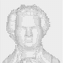
Visualize the recovered surface normal (p,q) as a needle map. A needle is the projection of a normalised surface normal (p,q,-1)/||(p,q,-1)|| on the image plane.The orientation of a needle and the orientation of the normal are equal. The length of a needle is proportional to sin(angle((p,q,-1), v)). The vector v=(0,0,-1) represents the line of sight.
Render the recovered object
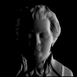
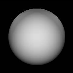
Once the surface normals are recovered they can be used to render the object using the Lambertian reflection model with an arbitrary illumination direction. Generate at least two images of the reconstructed object. The object should be illuminated from directions different to the light directions given in the input images.You may also be aware of visualisation tools such as VRML, ivview or plyview. They can also be used to visualise your results.
Have a look at http://www.cs.auckland.ac.nz/references/#vrml for information about visualisations packages.
Here are some example results to provide an idea of what to expect in the result.


eMail me! :)